Overview
Ensuring Accuracy in Spatial Analysis
A Mesophotic Dive into Coordinate Reference Systems
Fri, Aug 30, 2024
What is a Coordinate Reference System?
Coordinate reference systems can refer to either geographic coordinate systems or projected coordinate systems. Geographic coordinate systems describe locations on earth using a three-dimensional reference, and are used along with a specified map projection to create a projected coordinate system, which describes the same information on a two-dimensional surface (1) . Geographic coordinate systems use angular units such as degrees for measurement (often seen as lat/lon in R), and projected coordinate systems convert this information to linear units such as feet, meters, or kilometers as coordinates.
Coordinate reference systems require an origin (0,0) point, which is defined by projection parameters. The origin allows users to define where a point of interest exists on their map versus its real location on Earth. For example, (128, 14) has no meaning unless one knows where the origin point of a given map is. Defining the origin allows users to utilize different sources of spatial data by providing a framework for how they should be aligned and integrated (2) . Broadly, coordinate reference systems store and portray data in a manner which allows other spatial data to be seamlessly integrated into a map to provide meaningful interpretation.
Widely used Coordinate Reference Systems
Some of the most widely used geographic coordinate reference systems are WGS 84 (World Geodetic System 1984), NAD83 (North American Datum 1983) and UTM (Universal Transverse Mercator). In the United States, common projected coordinate systems are SPCS (State Plane Coordinate System) and LCC (Lambert Conformal Conic) (3) . WGS 84 is the standard for GPS receivers and most GIS applications, making it the most commonly used geographic coordinate system. UTM is a common plane grid system, although the choice of projected coordinate system depends on the specific application.
Different projected coordinate systems are used because the fundamental challenge of working with spatial data is representing 3D coordinates on a 2D plane. One could replicate this problem at home with an orange and some aluminum foil. Take a square of aluminum foil, draw three vertical and three horizontal lines on it, making a grid. It is impossible to wrap the orange in the aluminum foil while linking each pair of opposite lines without creasing or tearing the aluminum foil. Similarly, converting a 3D model of the Earth (an ellipsoid or sphere) to a 2D map must introduce some distortion to be used with confidence. Different map projections distort certain aspects of a map so that a user's target aspect of the 3D surface is portrayed accurately.
Tradeoffs Between Coordinate Reference Systems
Tradeoffs between projected coordinate systems primarily refer to the type of distortion introduced. Different projections will either distort shape, area, distance, or direction. In addition, compromise projections are those which attempt to minimize overall distortion (4) .
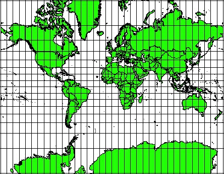
Conformal projections attempt to preserve local shapes and angles. For example, Lambert’s Conformal Conic projection maintains angles, shapes, and direction at small scales, yet increasingly distorts distances, scale, and area further away from standard parallels (5) . Another well known conformal projection is the Mercator projection. Both of these map projections are well suited to east-west orientation at mid-latitudes. The distortion present in either projection can be seen by comparing the size of Greenland to Africa on a Mercator map in contrast to an equal-area projection (6) .
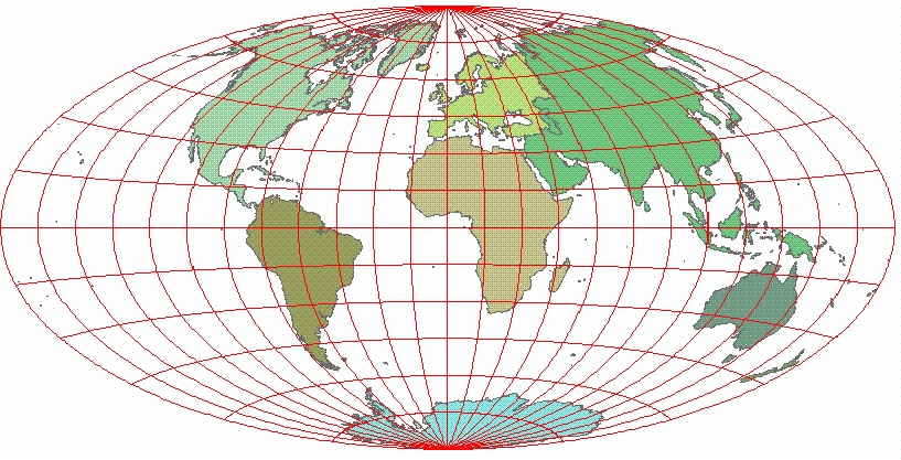
The three other types of projections are relatively straightforward in what they attempt to preserve when displaying 3D data on a 2D plane. Equal-area projections attempt to accurately represent areas of objects on a map. In preserving areas, these may distort shapes, angles, or distances of the map (7) . Two examples are the Albers and Mollweide equal-area projections. Both of these trade off equivalence for general distortion of shape, angles, distance, and direction (8) . Equidistant projections attempt to maintain accurate distance and direction along certain lines or from specific points (9) . One of the most common is the Azimuthal Equidistant Projection, which preserves both distance and direction from the center point of the map (aspect) (10) . Equidistant projections are not typically conformal or equal area, and scale is only true along straight lines from the center point. Finally, some map projections are able to preserve compass bearing, such as the Mercator projection which was originally created for sea travel (11) .
Picking a Coordinate Reference System
As coordinate reference systems were created for different use cases, choosing a coordinate reference system boils down to defining what the user requires of their projection. Depending on the project or analysis, different projections will be more useful than others, so careful consideration of the type of analysis will elucidate which projection will be most suitable.References
-
Azimuthal equidistant. Azimuthal equidistant-ArcGIS Pro | Documentation. (n.d.).
-
Coordinate reference system and spatial projection. Earth Data Science - Earth Lab. (2017, February 15).
-
Coordinate systems, map projections, and transformations. Coordinate systems, map projections, and transformations-ArcGIS Pro | Documentation. (n.d.).
-
Dempsey, C. (2022, July 1). Geographic Coordinate Systems. Geography Realm.
-
GIS Dictionary. Compromise Projection Definition. (n.d.).
-
GIS Dictionary. Equal-Area Projection Definition. (n.d.).
-
GIS Dictionary. Equidistant Projection Definition. (n.d.).
-
Jung, T. (n.d.). Compare map projections. Albers vs. Lambert conformal conic: Compare Map Projections.
-
Lambert conformal conic. Lambert conformal conic-ArcGIS Pro | Documentation. (n.d.).
Code for the visualization in this blog post can be found in the website GitHub repository.
This post was created by the 2024 OHI Fellows.